REMINDER: Context is key; this information should be taken as a guide only . The details of this article can vary based on the production and the creative intent.
Additionally, Netflix has produced a series of informative videos and modules designed to provide valuable insights into virtual production methodologies.
CAMERAS + CAPTURE FORMATS
NETFLIX APPROVED CAMERAS LIST
Netflix is committed to providing the highest level of image fidelity and quality to subscribers around the world. In order to achieve this, Netflix has carefully curated a list of Approved Cameras for use on Netflix Original productions. These “Approved Cameras” have undergone internal evaluation at Netflix in partnership with the manufacturer and meet the specified requirements listed below. Netflix works closely with the creative community in defining its approved camera requirements, setting thresholds based on extensive industry experience and guidance from globally recognized organizations such as the ASC (American Society of Cinematographers), BSC (British Society of Cinematographers) and AMPAS (Academy of Motion Picture Arts and Sciences). These base requirements are an amalgamation of opinions and aspirations from working professionals looking to push their craft and the industry forward. They aim at enabling creatives to produce their best work, unrestricted by technological limitations while future-proofing their efforts for generations with high-fidelity archival assets.
CAPTURE SPECIFICATIONS
When capturing plates for use with LED walls in a virtual production environment or post-VFX, we recommend always using a Netflix approved camera. This will not only guarantee the best image quality but will also ensure the smoothest experience while capturing and post-producing the content for its use. We understand that there are specific budgetary, technical or logistic situations whereby it will be hard to use an approved camera. A perfect example could be aerial or drone plate capturing, which is essential to keep the camera size and weight to the minimum, which means that the choice of the camera often falls outside of our approved camera list. For these reasons, we have extracted and outlined a series of specifications that should help you choose the best compromise and be aware of any potential tradeoffs. These should be reviewed by the Camera Department and Plate Supervisor to ensure all requirements are being met.
COLOR PRECISION
-
10-bit with 4:2:2 chroma subsampling or greater.
- Low bit depth images are prone to artifacts such as banding/posterization and quickly fall apart during regular grading operations.
Effects of banding across a smooth gradient due to low bit depth capture
- Chroma subsampling reduces color resolution by reducing chroma sampling per scanline. Image degradation due to chroma subsampling can be seen easiest near the edges of sharp color transition, usually resulting in an image with lower saturation levels.
- NOTE: If your project will require high levels of visual effects & compositing operations for the material being played back on the walls, you should strongly consider capturing in a RAW or uncompressed format. Lower chroma subsampling can cause issues quickly when integrating with CG-rendered content.
RECORD FORMAT
-
RAW or Scene Referred image data.
- Log encoding redistributes exposure code values to more efficiently retain shadow and highlight detail in bit-depth-constrained formats.
- RAW is generally defined as minimally processed pre-debayer sensor data.
- Captured color space/color gamut should be scene-referred rather than display referred. For example, REDWideGamutRGB/Log3G10, S-Gamut3/S-Log3, ALEXA Wide Gamut/Log C or V-Gamut/V-Log
-
When RAW or uncompressed image capture is not an option, we recommend lightly encoded intra-frame-based codecs such as ALL-Intra, XF-AVC, XAVC, etc.
- Intraframe compression analyzes and compresses each frame individually.
- Interframe compression schemes analyze two or more sequential frames in an attempt to retain only information that changes from frame to frame. While this can be advantageous for reducing data rates, it’s heavily prone to visible artifacts and is, therefore, not an approved capture format.
DATA RATE
-
Minimum recorded data rate of 240Mbps (Megabits per second) or 30MB/s (Megabytes per second) at a capture rate of 24FPS. This equates to ~10Mb per frame. As the frame rate increases, so should the minimum data rate. For example, if you’re shooting at 30FPS your minimum data rate will be ~300Mbps
- Certain codecs require a minimum data rate. For example, ProRes 422 HQ at 3840x2160 @ 24FPS has a data rate of 704Mbps. This is well above our minimum threshold and therefore acceptable.
- Low data rates stress compression schemes, often leading to unwanted image artifacts such as macroblocking.
Example of macroblocking due to low bandwidth image compression
RESOLUTION
-
Each camera in use (multi-camera array) must have a minimum active photosite count of 3840 x 2160
- Upscaling the content is not recommended. The capture resolution should match the resolution of your intended LED wall, plus around 25% of the maximum height of the LED wall canvas, to allow for the pixel mapping to be warped or reprojected without needing additional upscaling.
- Spherical (normal and fisheye) capture is highly recommended. Anamorphic lenses should be avoided. Please contact us directly if considering otherwise.
- Camera arrays are common practice in this space, but not a requirement. Please review our Approved Camera list for camera selection.
- Square pixel aspect ratio.
SENSOR READOUT SPEED
-
The active readout speed of the camera sensor should be less than ~18ms when capturing plates in order to limit rolling shutter artifacts, such as skew. Global Shutter sensors eliminate rolling shutter artifacts and may be advantageous in certain situations.
- The readout speed of a sensor is not to be confused with shutter speed, shutter angle or integration time. A sensor’s readout speed influences the severity of rolling shutter artifacts. A longer readout speed increases rolling shutter artifacts such as jello/skew. Common to the majority of standard rolling shutter-based CMOS sensor designs, readout times increase as vertical resolution increases.
- Please note, that all of our Approved Cameras have capture settings that meet or exceed our recommended minimum readout speed of ~18ms.
Example of Rolling Shutter Artifact - Skew
CAMERA ARRAY CONFIGURATIONS
The use of multi-camera arrays is not a requirement. In many instances, plates can be captured with a single camera system. Every show has its own requirements, and therefore, capturing specs should be adjusted as needed. When and if a multi-camera array is necessary, there are a series of technical considerations which will influence the best camera and lenses to use and their repsective setup.Please speak with the Plate Supervisor, VP Supervisor, VFX Supervisor, and DP to assess these needs.
STANDARD CAMERA ARRAY EXAMPLE
Here’s a non-exhaustive list of multi-camera array examples.
-
9x cameras
- 3x Front-facing cameras generally mounted to the windshield of the car
- 5x Back facing cameras mounted on the back windshield of the car
- 1x Camera mounted to the hood of the car facing upwards (Generally used for reflections)
-
7x cameras
- 3x Front-facing cameras generally mounted to the windshield of the car
- 3x Back-facing cameras mounted on the back windshield of the car
- 1x Camera mounted to the hood of the car facing upwards (Generally used for reflections)
-
4x cameras
- 3x Front-facing cameras generally mounted to the windshield of the car
- 1x Camera mounted to the hood of the car facing upwards (Generally used for reflections)
- 3x Front-facing cameras generally mounted to the windshield of the car
CAMERA OVERLAP REQUIREMENT
A minimum 25-degree FOV (Field of View) overlap is required for stitched plates.
Please consider a 30% overlap between cameras.When configuring your camera array ensure the optics being used and the positioning of the cameras achieve this.
Appropriate rotation of each camera relative to its nearest neighbor will be dependent on each camera’s physical dimensions, active sensor area, and lenses.
WHY IS OVERLAP NECESSARY?
Without an overlap of FOV between cameras in an array configuration, stitching images together becomes problematic. Once the lens distortion characteristics are removed from each frame, large gaps in the FOV may become apparent. To avoid gaps in coverage and slight errors in camera alignment it’s important to ensure a healthy amount of overlap is achieved. This makes stitching plates together from an array a much smoother affair for the provider/ vendor prepping the content.
Increasing the overlap of FOV between cameras may require the use of additional cameras in the camera array configuration, wider focal length lenses with wider angles of view and/or making adjustments to the camera positioning/angle of each camera configured in the array.
Camera arrays can be configured in an infinite number of ways all specifically designed for the production's current needs. The below images are a great example of one high-end solution used previously on Netflix productions.
EXAMPLE CONFIGURATIONS
When designing/selecting the appropriate camera array rig configuration, you may want to consider examples like the following:
- Driving Plates Rig Gallery
- BROWNIAN Motion
- Radiant Images - AXA Camera Array
- Radiant Images - AXA Car Mount Configuration
- Radiant Images - Sense 9x Camera Array
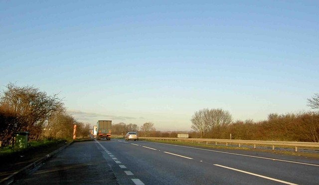
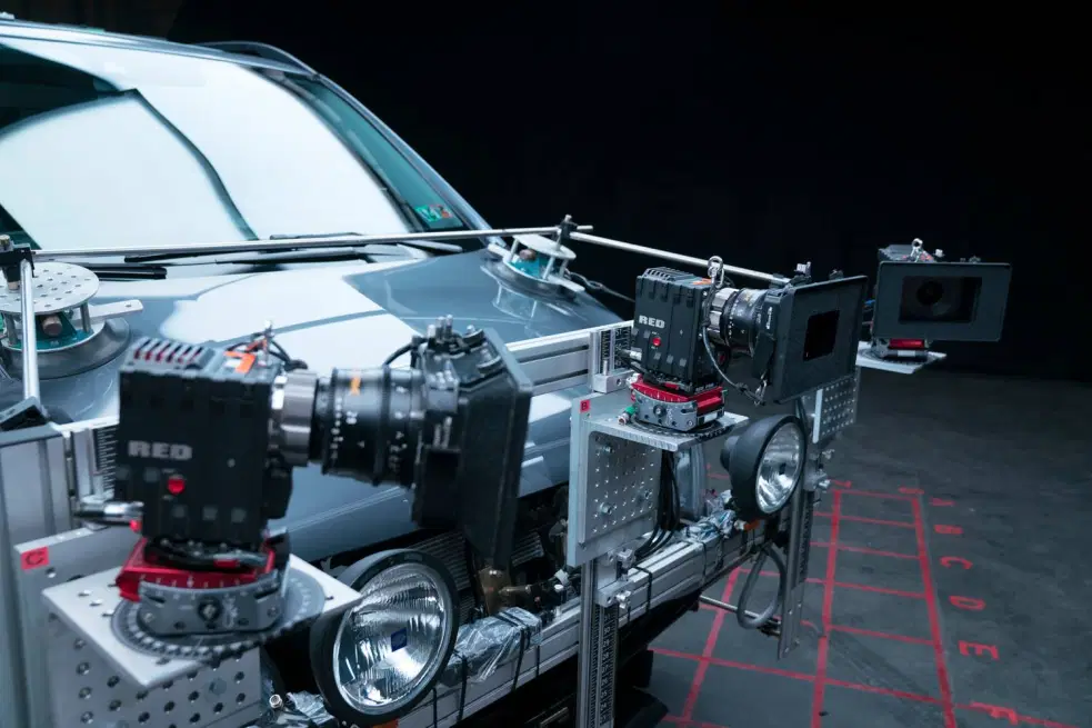
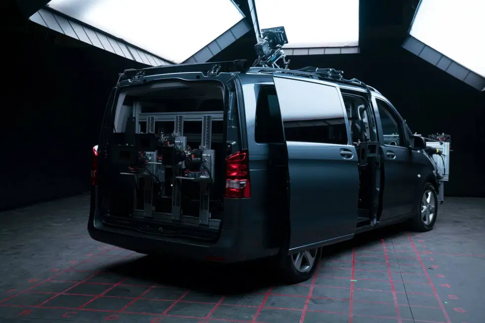
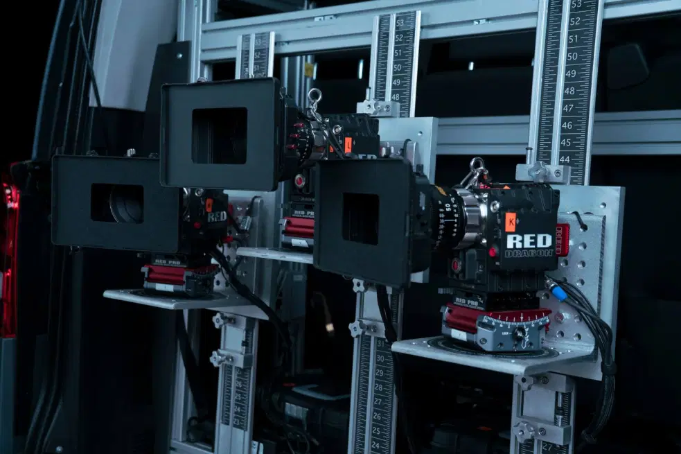
EXAMPLE PLATE VAN
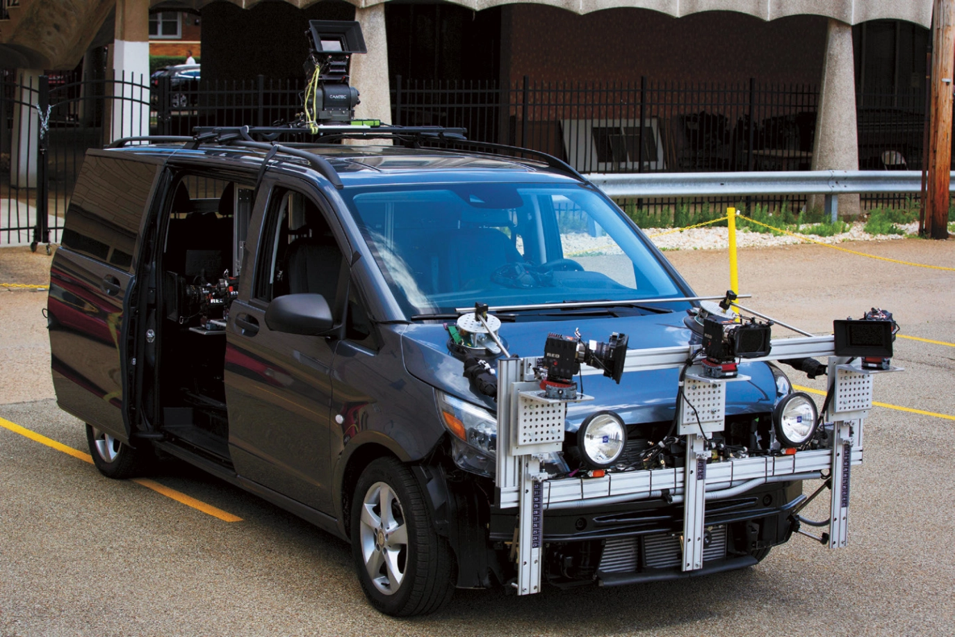
Photos courtesy of RED.
Photos courtesy of RED.
Photos courtesy of RED.
Photos courtesy of RED.
USING FISHEYE LENSES FOR YOUR ARRAY
Fisheye lenses have historically been avoided in single-camera plate captures and array systems. The reason was primarily due to the extreme lens aberrations at the edge of the frame and the artifacts created by correcting the lens geometric distortions. However, fisheye lenses have always attracted plate capture providers due to their extreme field of view coverage and, therefore, their ability to remove the need for stitching or reduce the need for cameras in an array to the bare minimum (2 cameras with a 280º fisheye lens can provide a full 360º plate). Given today’s increased native camera resolution beyond 4K and the advancements in scaling algorithms, fish eye lenses are now considered a valid option for plates. However, fisheye setups have some limits: standard spherical lenses with multiple camera points in an array benefit from a shifted perspective and pivot point for each camera. When doing pixel mapping of a single camera with fisheye, emulating a camera position in a space different from the one used to capture the plate will be limited by having a single point of view. On the contrary, multiple cameras in an array will allow for better fake perspectives despite - as discussed above - adding the complexity of stitching high-resolution plates.
CAPTURE FRAME RATE
When capturing plates it’s highly recommended that your capture rate is, at minimum, matched to your show’s intended frame rate. For example, if the production plans on shooting at a frame rate of 23.976FPS, your plates should also be captured at a rate of 23.976FPS. The same holds true for alternative frame rates such as 25FPS or 29.97FPS etc. Shooting at a multiple of the shooting frame rate is also an option and allows to control the resulting motion blur; see HIGH FRAME RATE section below.
WHY DOES THIS MATTER?
Frame rate conversion requires motion interpolation (diagrammed below) which will degrade your footage and can often lead to unsightly motion artifacts. In simple terms, motion interpolation requires complex algorithms to calculate missing image data between captured frames. These calculations are never perfect and should be avoided whenever possible.
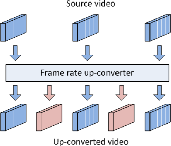
Matching frame rates limits the necessity of downstream interpolation such as pulldowns being applied to your plates. Speak with production and make sure you’re aligned regarding the proper capture rate for your show.
HIGH FRAME RATE
When shooting plates for ICVFX, it could be beneficial to capture and playback your plate at 2x or 3x times your show’s intended framerate; this will provide a more realistic motion blur reproduction in the LED volume but will considerably increase the burden of the plate playback system. Speak with the LED wall provider to make sure of your system's capabilities.
EXPOSURE/LIGHTING MATCH
When capturing plates, the most critical aspect is to record as much dynamic range as possible, retaining the scene data.
RESOLUTION MATCH
The capture resolution of your plates should be greater than or at least equal to the resolution of your LED wall. Upscaling is not recommended when outputting to an LED wall configuration. Improper upscaling could lead to unsightly aliasing artifacts across the display (see below).
Each camera in use (multi-camera array or otherwise) must have a minimum active photosite count of 3840 x 2160. Once stitched, the total resolution of your plates should be 25% bigger than the maximum height of the LED wall canvas to allow for the pixel mapping to be warped or projected. This should prevent the need for upscaling when outputting to your LED wall configuration.
- Spherical capture is highly recommended as it reduces potential complications arising from optical distortion and aberration. Please contact us directly.
- Camera arrays are standard practice in this space. Please review our Approved Camera list for camera selection.
LOW RESOLUTION CAPTURE MAY LEAD TO ALIASING/MOIRE PATTERNS
Examples of aliasing/moire artifacts
-
Examples of aliasing/moire artifacts
PERSPECTIVE MATCH
When positioning your camera(s), be mindful of the perspective. How are the cameras angled? How high or low to the ground are the cameras positioned? What lenses are you using? Are they relatively distortion free? Will the perspective of your plates be in conflict with the creative intent of the DP? Be sure to get alignment ahead of time to avoid these pitfalls.
WHY DOES PERSPECTIVE MATTER?
Mismatched perspectives will not only cause headaches for everyone on set, but for the viewers at home as well. Imagine plates that were shot from a high angle being used by a DP intending to shoot from a low angle. This mismatch in perspectives will throw the whole scene off.
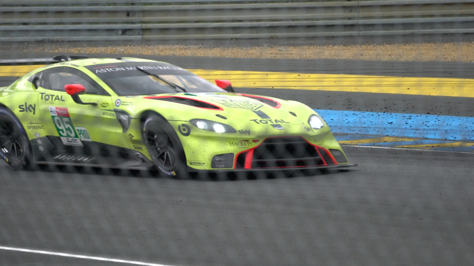
For car process work specifically, pay special attention to how high the cameras are mounted. If the camera(s) are mounted to the roof of the car (vs. the lower hood of the car), they may be too high to capture the appropriate perspective of someone traveling within the vehicle. Improper perspective and angles can be extremely challenging for the content provider VFX teams to correct.
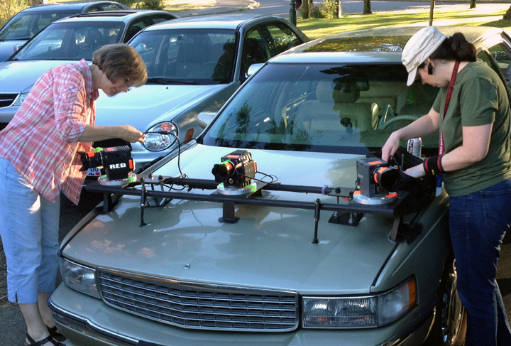
Example: Camera bodies positioned at the front of the car creating low angles for better perspective match
LENS DISTORTION? WHAT IS IT AND WHY SHOULD I AVOID IT?
Take a look at the images below. The square grid on the left demonstrates a real world “object” with zero distortion characteristics. The two grids to the right of the “object” demonstrate the differing types of distortion that occur when viewing any object through a lens.
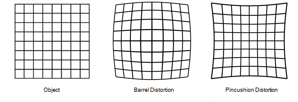
No lens is perfect. Every lens on the market exhibits some level of distortion in one form or another. However, some lenses perform better than others. For instance, longer focal length lenses tend to show less distortion characteristics vs. wider focal lengths.
Is distortion always a bad thing? Not necessarily. In fact, many DPs select lenses based on their unique distortion characteristics and the subtle imperfections they impart on the image. But when it comes to capturing plates for use with LED walls, distortion should be avoided whenever possible. Discuss lens selection with the DP and VFX teams to ensure you’re using the right lens for the job. Many lenses are capable of providing valuable information such as aperture, focus distance, focal length, shading/distortion etc. in the form of metadata utilizing popular communication protocols such as Cooke /i Technology, ZEISS eXtended Data and ARRI LDS. Collecting and preserving this lens metadata can increase the efficiency and accuracy of the VFX team's work. It's highly recommended to leverage lens metadata when possible.
MOTION CADENCE MATCH
How fast is the subject matter of your plate(s) moving across frame? Is judder being introduced? Does the rate of motion match the creative intent of the scene? For example, should this car appear to be driving down the street at 120 MPH or 30 MPH? Does the shutter speed of your plates match your intended project settings? Is the level of motion blur being exhibited natural, relative to your scene? Are rolling shutter artifacts being introduced? Does the image appear skewed in one direction?
WHY SHOULD I CARE ABOUT MOTION CHARACTERISTICS?
JUDDER
Subject matter moving across frame too fast can introduce judder and is highly distracting to viewers. This is a well known artifact that can often rear its head during camera pans that are performed too fast. If judder is being exhibited, try slowing down the speed at which your subject matter is traveling across the frame when recording your plates.

Example of Judder
MOTION BLUR
Audiences have grown accustomed to a certain level of motion blur in moving pictures. If the background blur doesn’t match relative to the foreground elements, it will have an unnatural appearance your viewers will likely pick up on. Take this into account by matching project shutter speeds. Keep in mind that it’s relatively simple to add motion blur digitally, but very difficult to remove it.
Differing levels of Motion Blur
ROLLING SHUTTER ARTIFACTS
Most modern digital cinema cameras employ a rolling shutter-designed CMOS sensor. It’s likely the cameras being used to capture plates have a rolling shutter. With a rolling shutter design, it’s possible to encounter artifacts such as skew when the subject matter is moving too quickly across the frame. Keep this in mind while shooting and avoid these artifacts as much as possible. Global shutter sensors do not suffer from this because, unlike Rolling Shutter-based sensors that read out sensor data line by line successively, Global Shutter sensors read out all the data for a particular frame simultaneously.

Example of Rolling Shutter Artifact - Skew
IMAGE STABILIZATION
When capturing plates, it’s very important to ensure proper image stabilization. Shaky footage may require heavy post-processing work to stabilize. This is not only time-consuming and costly but will also lower your captured resolution since digital stabilization generally requires cropping in on the image. Keep this in mind when configuring your camera system and selecting your capture format.
Furthermore, think about the context of your scene. Are you shakily off-roading through the jungle or smoothly coasting along a paved street? Each scenario may call for a different level of movement to match contextually. Try to understand where and how the plates fit the overall scene before making too many decisions.
DEPTH OF FIELD MATCH
To avoid mismatched depth of field, think about the scene ahead of time and align with the DP on their intended DOF. The focus falloff and distortion characteristics of the plates need to match those of the scene for it to be believable. In most scenarios, it’s advised to capture plates with a deep depth of field (i.e., everything in focus). This allows for VP teams to dial in blur characteristics as necessary.
Example of intentionally mismatched Depth of Field from a Split Diopter
SENSOR SYNC FOR STITCHED PLATES
Maintaining sensor sync across all cameras in an array is very important. Sensor sync enables each sensor in the configuration to capture simultaneously, preventing frame mismatches between systems. Please ensure the camera systems you’re using for your array are capable of sensor sync. In most cases, sensor sync is achieved via Genlock input from a dedicated Genlock-generating device.
WHY SHOULD I CARE ABOUT GENLOCK OR SENSOR SYNC?
Similar to the way Genlock is used across multiple LED wall panels to ensure proper playback, Genlock can also be used to synchronize the read/reset cycle of CMOS sensors across multiple camera systems. Without sensor sync, all camera systems in an array will be capturing frames with temporal offsets of varying degrees. These offsets will lead to additional VFX work when attempting to align and stitch images across multiple planes of view. Don’t burden your VFX teams/ content provider with extra work! Be a team player and get it right in camera as much as possible.
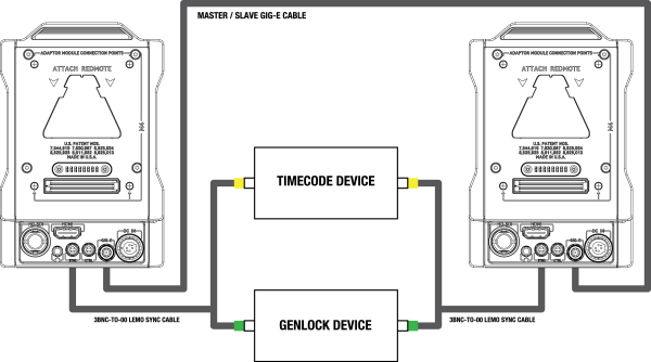
Example of Genlock being used to achieve sensor sync
Photo courtesy RED Digital Cinema
NOTES AND METADATA COLLECTION
The collection of notes and metadata is vitally important to the production. Detailed notes of array setup, camera settings, vehicle speed, and lens settings should be kept throughout the capture process and provided to the Editorial and VFX teams alongside the captured footage. Depending upon the project, it is often the VFX Data Wrangler’s job to collect this information. For VFX-heavy shows, data collection is usually handled by the VFX Data Wrangler (often working closely with the 1st or 2nd AC). If there is not a VFX Data Wrangler, this information can also be captured by the camera department.
EXAMPLE NOTES/METADATA:
- Camera Make/Model
- ISO
- White Balance
- Shutter Speed
- Frame rate
- Resolution
- Codec
- Color Space
- Gamma Curve
- Lens Make/Model
- Lens Focal Length
- Lens Aperture
- Lens Focus Distance
- Witness Photos
- Camera Placement - Height from Ground, Distance from Scene, Angle
- Speed of Vehicle
- Location
- Time of Day
- Sun Position
CONFORM SPECIFICATIONS
The ins and outs of conform, color, and editorial requirements for LED-based virtual production are varied and complex. They can range from selecting, editing, and stitching your own driving plates, to using stock footage, to completely computer-generated graphics. There is no “one size fits all”, and the following sections are meant to be a jumping-off point for your production and vendors to discuss plans and constraints.
OUTPUT CODECS
- Delivery codec should be selected based on the playback server you’re using. Not all codecs are created equally for different operating systems in different software packages on different graphics cards.
- Choose a video codec with a minimum of 10 bit depth. This is a requirement for any HDR specification to avoid banding & color reproduction issues. At a minimum, your output codec should attempt to mirror your capture settings if you shot compressed, or the highest option possible if working from RAW footage.
- Choose a color space and an encoding transfer function that can retain as much dynamic range of the camera sensor, such as the native color space of the camera used for capturing the plate or ACEScct (remember it requires a minimum of 12bit encoding), or Linear floating point (today only available when using EXR).
-
Common delivery codecs & some notes:
- ProRes 422/444 - compressed
- Notch LC - compressed
- EXR - uncompressed
- DPX - uncompressed
Please see Content Playback Technology for more specifications.
COLOR PIPELINE
The color pipeline and workflow on an LED-based shoot is complex, varying, and touches every element of software and hardware described in this guide. The biggest note here is that the LED panel is a light source to be captured in camera, not a display to be viewed with the human eye. As such, requirements and color workflows will differ from setup to setup. The objective is that the entire pipeline should retain as much dynamic range and color details of the original scene captured in the plates, as well as outputting a “linear” signal out of the LED wall, handling out-of-gamut or clipped values without affecting too much the rest of the image. The LED wall calibration is essential, both using the Image Processor calibration procedure to calibrate each tile/panel of the LED WALL, and a camera calibration workflow that will adjust the entire output of the LED wall to what the main camera used on set will be perceiving. To that scope, Netflix developed and open-sourced a tool called OpenVPCal, which aims to use the shooting camera as a colorimeter to calibrate the output of the LED wall and correct for the camera metamerism and EOTF tracking. Always preview and judge the output as captured by the camera, not how the panels appear on set to your eye.
This workflow will be described in detail in upcoming, separate documentation - but below are some quick checks to act as conversation starters as you plan your shoot.
- Know your LED specs - see LED Panel
- Maximize the calibration capabilities between your Image Processor / LED Panel / Camera
- Know your Primary Capture Camera (both for LED panel content as well as principal photography camera/lenses)
- Ideally, you would output your content with an Output Transform parameterized for your LED panels and optimized for capture in camera, avoiding any creative tone mapping that would disrupt the wall's linear output.
- Have a plan for minor correction on set - white point, exposure, contrast, etc.
For example:
- LED Panel Max Nit Level: 1500nit
- RGB primaries: P3
- Transfer Function: PQ/Gamma
- Black Level: 0.008nit
- Primary Camera: ARRI Alexa Mini LF
In this example, you could create an Output Transform in PQ P3 @ 1500 nits. It is ideal to be able to check and finalize on the panels.
Stay away from ‘creative’ grades for content on the LED panels unless they are intended to change the “scene values” (eg a day for night) - you’re effectively ‘double-lutting’ the content. All you should need are basic scene-referred corrections (exposure, white balance) and some minor CDL controls (slope, offset, power, saturation) used as “blending corrections” to better integrate the output of the wall with its foreground In some instances, highlight and shadow rolloff, as well as perceptual gamut mapping, might be necessary, but should only be used to contain the dynamic range and colors that cannot be correctly shown by the LED wall. Ensure that the EOTF used to map the content matches your processor and LED panel so that the proper inverse is performed.
STITCHING OR SINGLES
Every time you shoot with an array of cameras, we suggest providing the stitched plate as well as the individual single plates so that these can be used to overcome artifacts caused by the stitching such as ghosting or parallax problems.